Supervisory Switch Wiring Diagram
Light 24v is put out when valve is close to 20° direction. The model tts is a water tank temperature supervisory switch preset to give a low temperature signal at 40°f/4,5°c and a high temperature signal at 140°f/60°c (±5°f/3°c).

Sprinkler Flow Switch Wiring Diagram Free Wiring Diagram
Nema 6p enclosure allows the device to be mounted outdoors, even in areas subject to flooding.

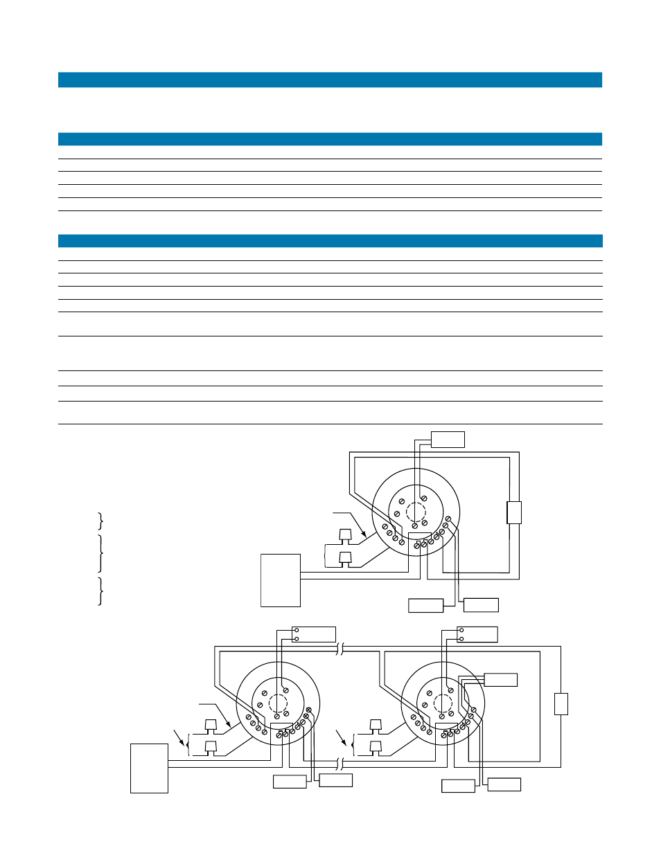
Supervisory switch wiring diagram. Supervisory switches are not a substitute for insurance. If two switches are provided, the second switch shall be set to operate at a 50 psi (3,5 bar) on a pressure increase. 3) the switch unit shall contain spdt (form c) switch(es).
For wiring a switch, you must have these tools and equipment. The model wosy contains two synchronized switches enclosed in a durable terminal block. There are two switch in gear box, one controls indicator light and the other connects to.
Single leads auxiliary equipment voltage source blue yellow orange green lead provided is ground for switch housing switch rating: Electrical relay diagram and p&id symbols. It is ul listed and fm approved.
One switch shall be set to operate at 30 psi (2,1 bar) on a pressure decrease. Delivery inspection after opening the carton,. Weflo ul / fm supervisory switches for os&y gate valves are designed for both indoor and outdoor use.
For "nc"switches, the circuit should be "no" switches should show a continuous closed circuit indicated by an. A 24vdc supply for an output stage may need to be reduced to 5v or 33v for logic circuits driving. All wire is supervised unless otherwise noted.
Switch 1 co m co m ab ba switch 2 contact ratings 125/250 vac 24 vdc 10 amps 2.5 amps sup. You see, one block made by dotted lines in the above pic, one block is the the breaker ( shown 52 a and 52 b, breaker auxiliary contacts and a trip coil) and another block. Connect a continuity tester such as a test light, buzzer, or similar device, to the switch leads.
15 amp light switch wire nuts utility knife Corrosion resistant outside screw and yoke valve supervisory switch. Section 4 reversing the action of pibv2 1.
Shows specificiations for standard configuration. Warning the limitations of supervisory switch alarm devices 3. Cap unused leads with wire nuts and tuck inside junction box (not provided) note:
The efficiency of linear power supply is 40 to 50. Building owners should always insure property and lives being protected. 14 transfer switch schematic diagram.15 troubleshooting.
Supervisory circuit wiring diagram (switch position valve full open) switch 1: 3 ways dimmer switch wiring diagram basic 3 way dimmers switches a 3 way dimmer switch is very sim light switch wiring ceiling fan switch 3 way switch wiring. The output of the dc power supply is used to provide a.
All wiring must be to local code. Switch bb com com sup. Warning the limitations of supervisory switch alarm devices 3.
Above is the wiring diagram of tcs relay wired to trip circuit of the breaker. Switch contacts shall be rated at 10.1 amps at 125/250vac. Single light between 3 way switches power via light how to wire a light switch home electrical wiring light switch wiring diy electrical.
Wiring — see figure 6, page 4. And two relay operated contacts that provide supervisory control of external loads. Wiring a light switch in this section, we will talk about how to wire a light switch.
Configuration options may change specifications. 2n3055 variable dc power supply circuit and. Typically, we purchase a switch from the market but for some unique situations, when you have to make it by your hand, then follow these steps.
Butterfly valve with supervisory switch model: Loosen the three 3/ 16˝ hex (socket head) screws on the top of the black switch When grounding is required, clamp wire with the screw in hole located near conduit entrance.
Supervisory switches are not a substitute for insurance. Corrosion resistant control valve supervisory switch. Conductors must test free from all grounds.
Building owners should always insure property and lives being protected. Eton 50cc atv kill switch wiring diagram e ton recommends that both the operator and the adult supervisor attend an atv safety instruction course wiring diagram 18 manufactures warranty 19 e ton recommends you take an atv riding course before you first ride your vehicle,

Smart Plug Wiring Diagram Complete Wiring Schemas

Why Does Closing Some Gatevalves Show Trouble?
Valves Merit Fire and Power Piping System Pvt. Ltd.

Fire Alarm Tamper Switch Wiring Diagram Wiring Diagram

Carel Pressure Transducer Wiring Diagram / Innovative Cold

Wiring A Proximity Switch Brilliant An Example, An
Microprocessor Switch Circuit Diagram Wiring View and

OSYSU Installation YouTube
20 Images Sprinkler Flow Switch Wiring Diagram

Microprocessor Switch Circuit Diagram Wiring View and
B114lp typical wiring diagrams, 2151 photoelectronic

How do I Wire a Replaced Tamper Switch?

Wiring A Proximity Switch Top Allen Bradley Switch Wiring
UL / FM Supervisory Switches Tamper Switch


Plc Scada Wiring Diagram

Plc Scada Wiring Diagram

Potter tamper supervisory switch by Mohannad Faysal Issuu
19 Luxury Tamper And Flow Switch Wiring Diagrams


Ps10 Tyco Potter Pressure Type Waterflow Alarm/supervisory